Keepsake: Wiring
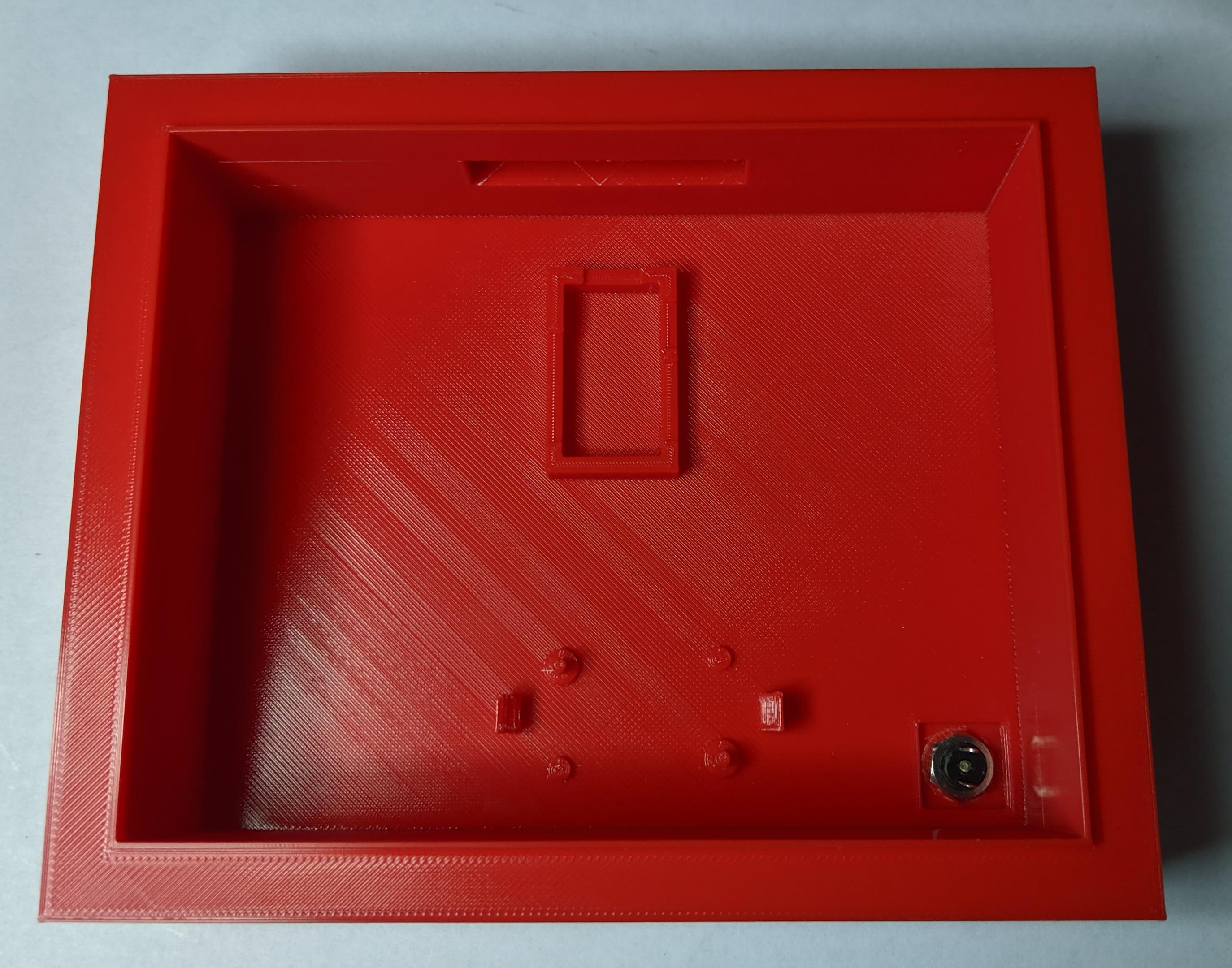
Once the components are fitted into the toolbox and frame, wires can be measured to ensure a clean fit. The wires should not be tight, nor should there be too much slack that cables are coiled into a corner.
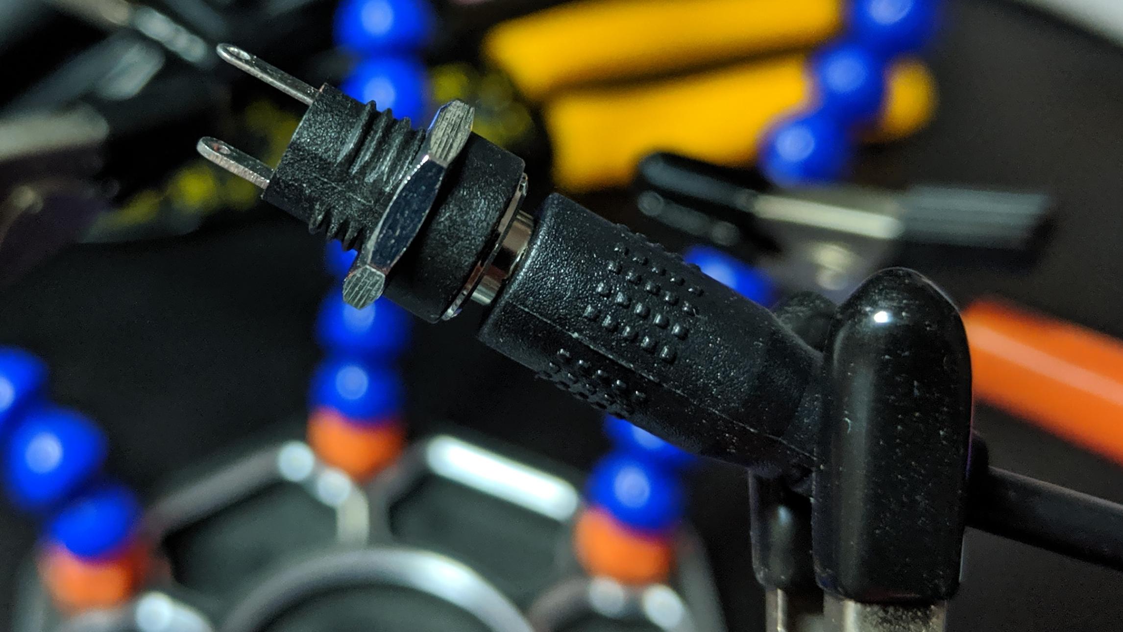
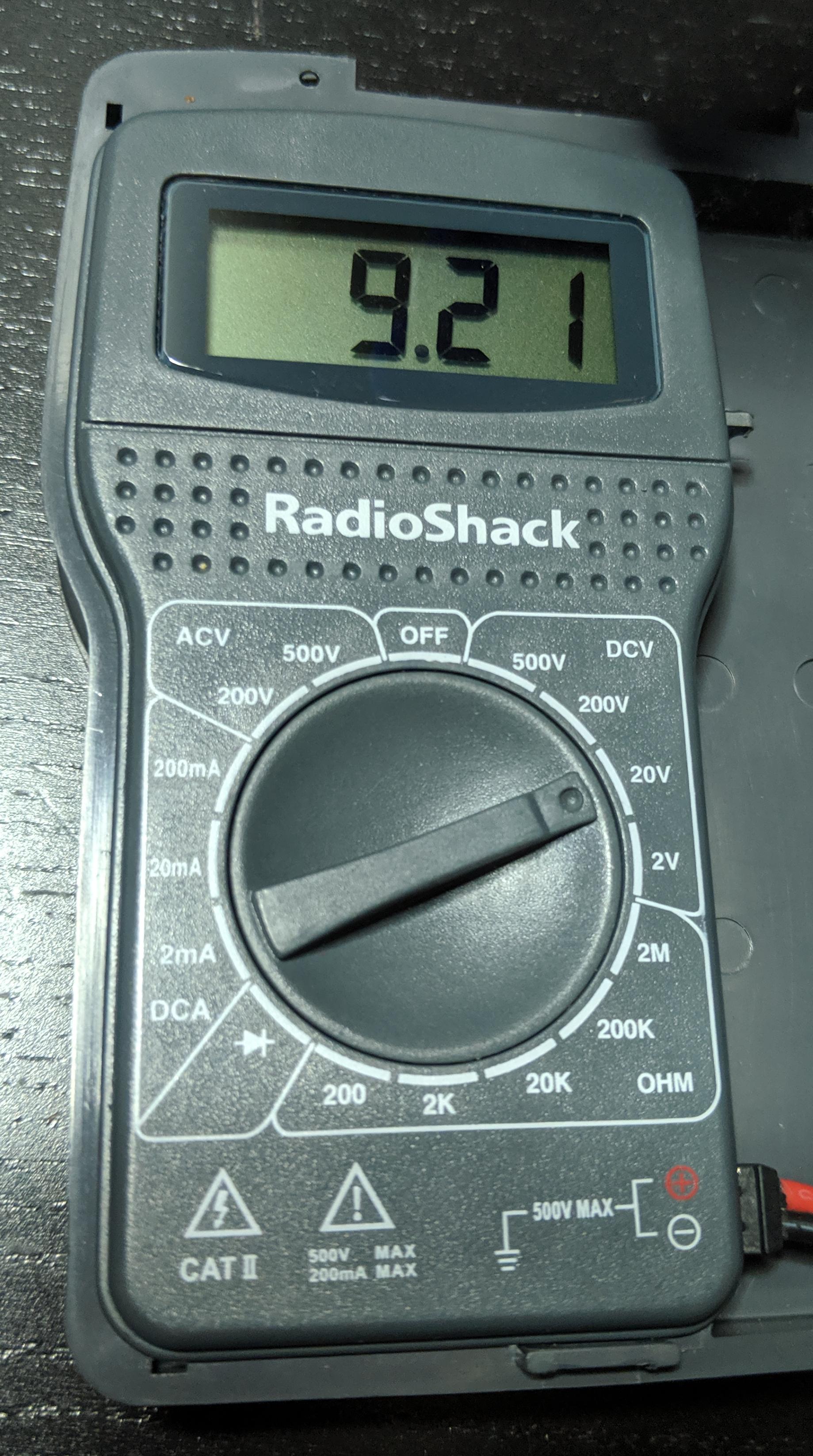
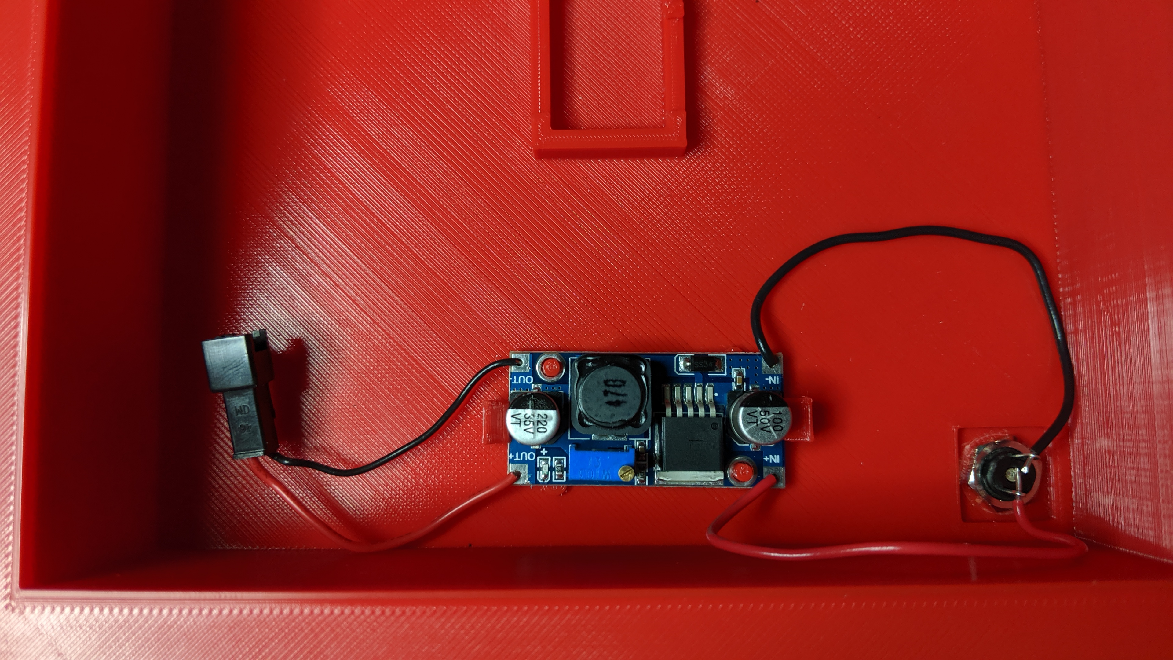
DC Voltage Regulator and Microcontroller
From the power jack to the voltage regulator, then to the Arduino Pro Mini microcontroller. The buck converter was configured to output 5.0 volts, which can go into the VCC pin on the microcontroller, rather than the RAW pin. The microcontroller has its own voltage regulator, which can handle the 12 volts from the AC adapter, but I want to keep the electronics from frying due to a voltage spike. Not likely to happen, but better safe than sorry.
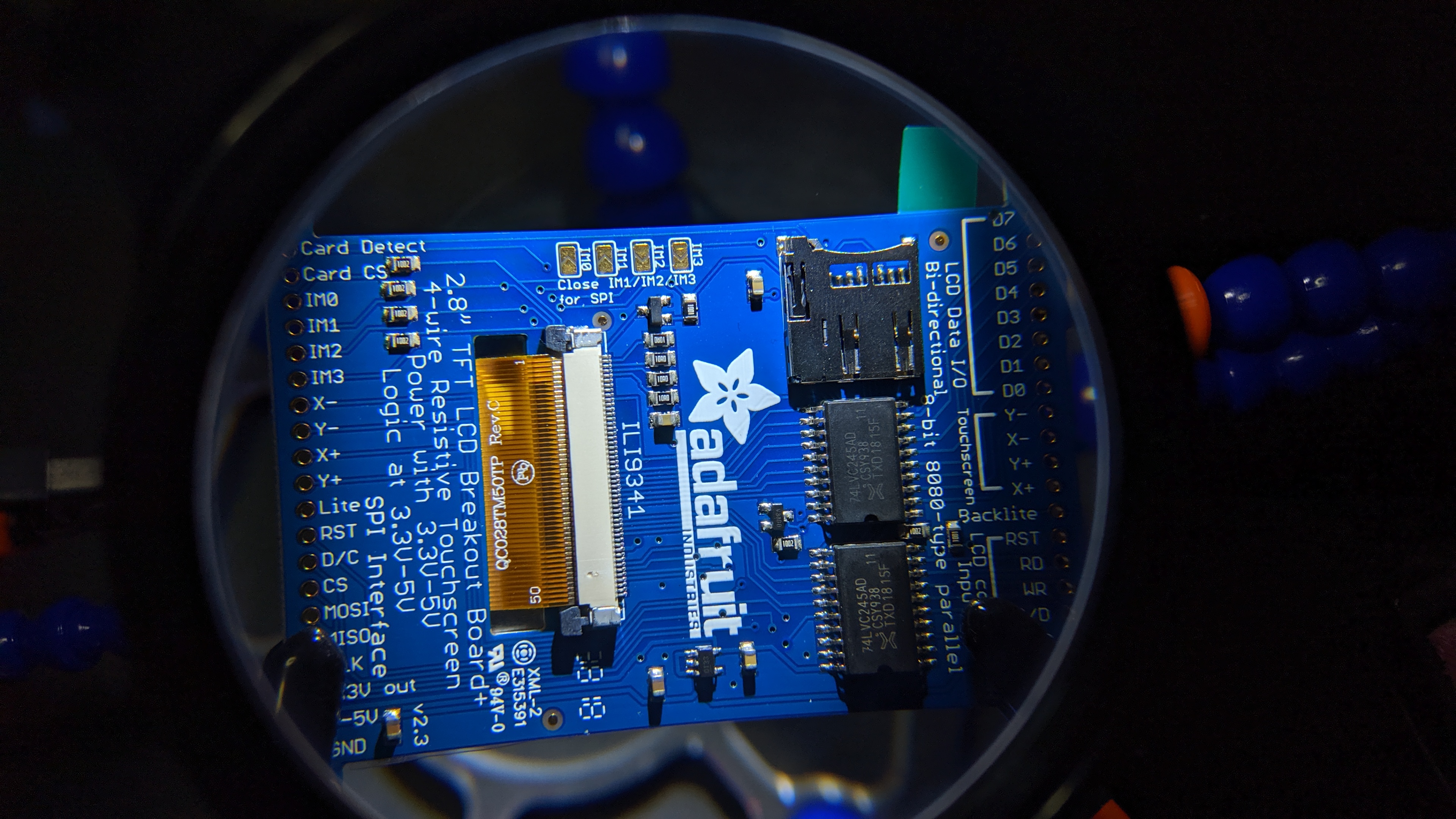
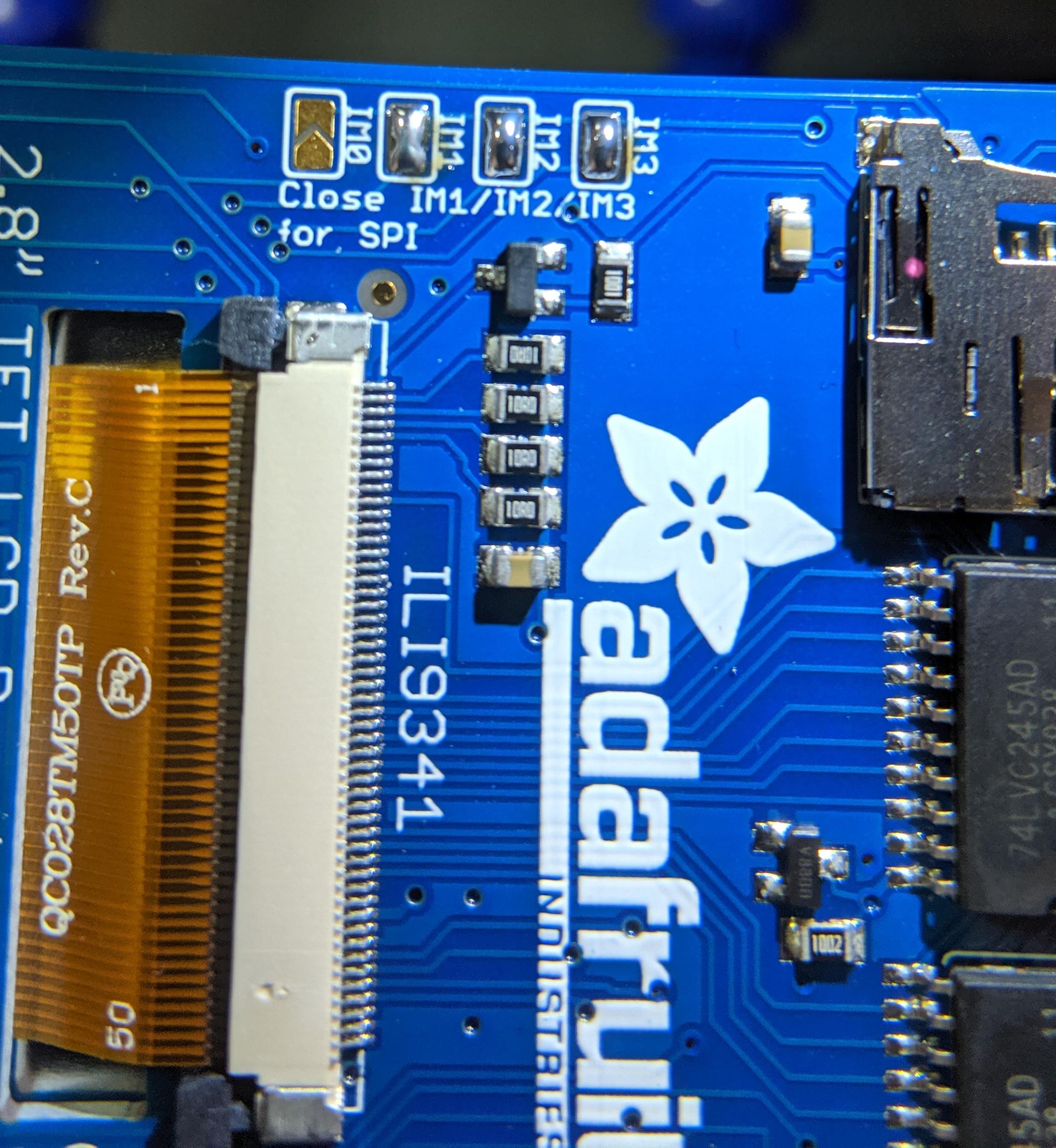
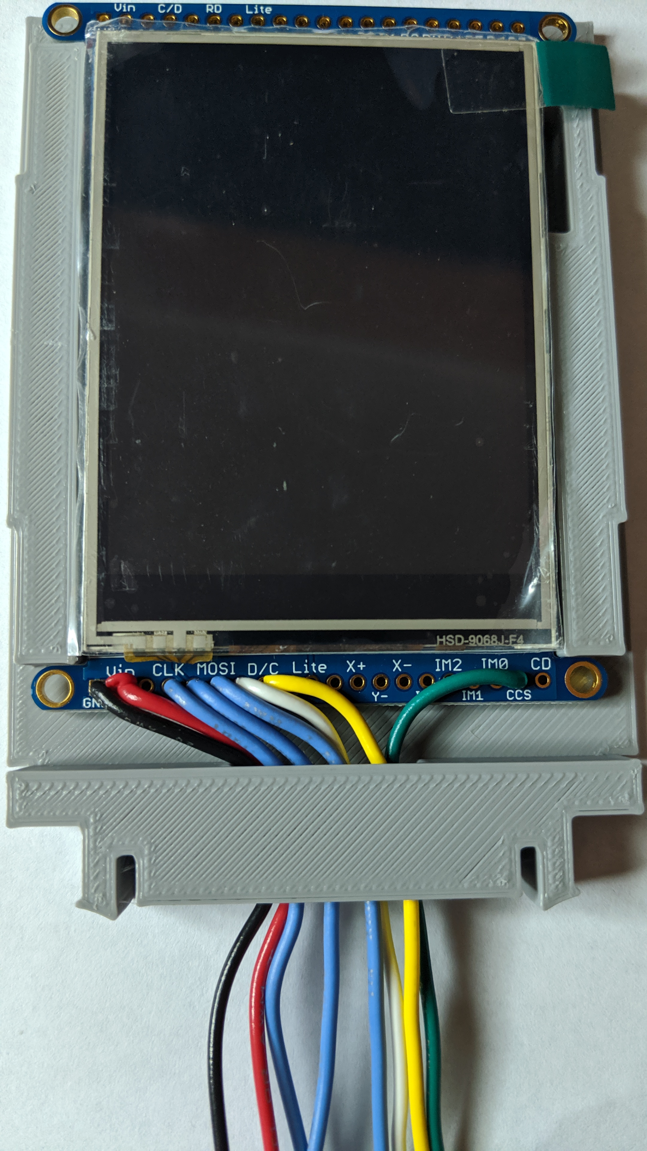
TFT Display
The display has 2 pins for power (VCC and GND), along with 6 communication pins. The Vin and GND pins will be tapped into the voltage out of the buck converter, providing 5v power to the TFT display. The rest of the pins will be connected as follows:
| TFT Display | Arduino Pro Mini |
| Serial Clock (CLK) | D13 |
| Master In Slave Out (MISO) | D12 |
| Master Out Slave In (MOSI) | D11 |
| Chip Select (CS) | D10 |
| Data/Command (D/C) | D9 |
| Card Chip Select (CCS) | D4 |
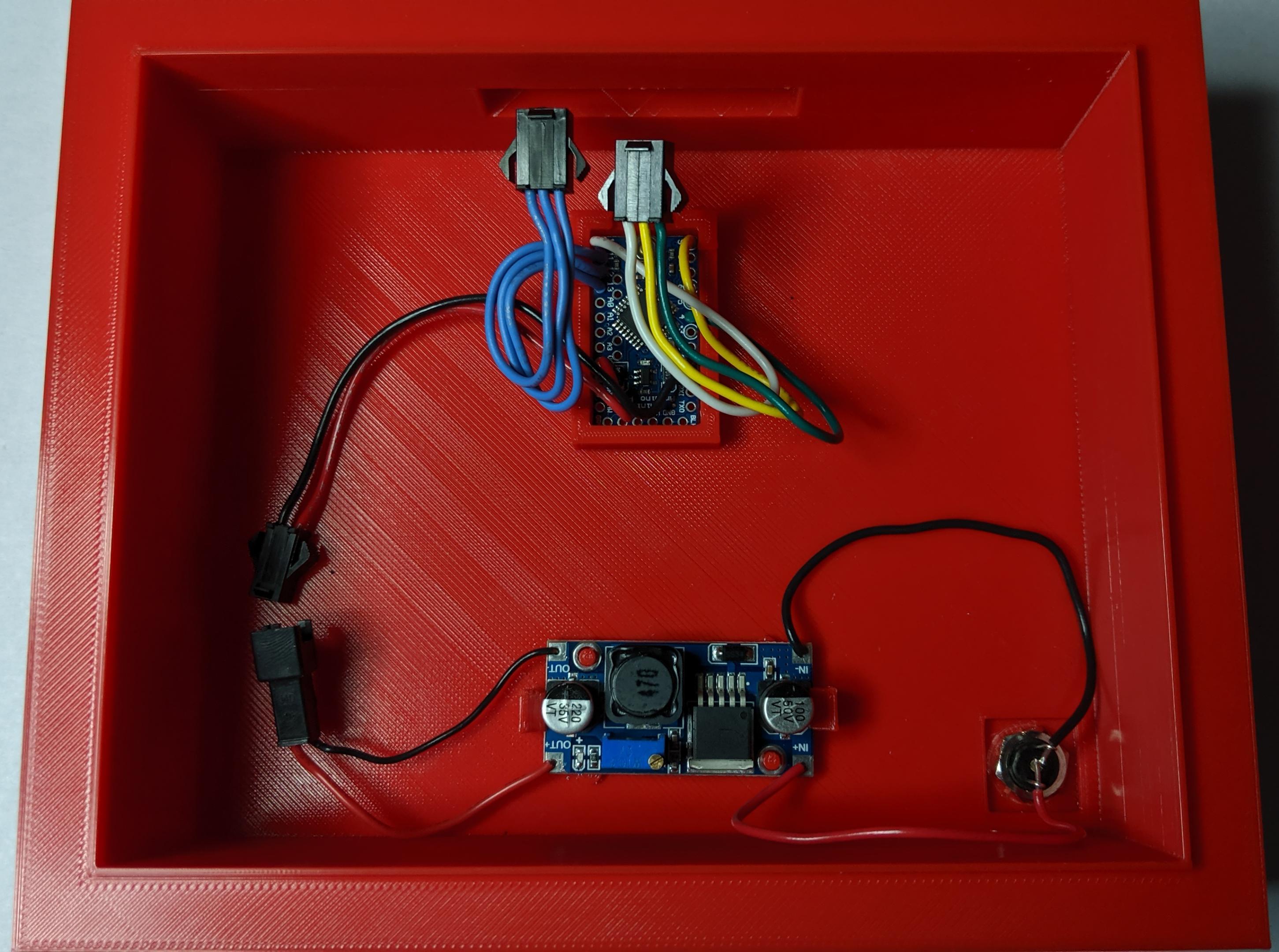
Dupont Connectors
This is a love-hate relationship: Dupont connectors are great for connecting parts, but crimping the wires and securing insertion can be a hassle. Using the Dupont connectors allows me to swap out a component, without having to cut wires, or desolder from other connections.
RESULTS